The Raspberry Pi Powered Speaking Doorbell – Part 3: Text to Speech

In Part 1 we looked at a simple input circuit to isolate our Raspberry Pi from our doorbell circuit and in part 2 we looked at making a camera overlay appear in Kodi. Next, we’ll look at building the text to speech server.

Please note that the following blog post uses code snippets from my Github project. You will need to clone or download the full source code to run the examples.

With my home setup, I have a dedicated media PC in the lounge which runs Kodi on Windows. It is connected to a Yamaha receiver which is permanently on. The doorbell circuit, however, is connected to a Raspberry Pi. In my case, it makes sense to have the audio for text to speech play over the media PC. But how do we trigger text to speech on the media PC from the Raspberry Pi when someone presses the doorbell?

To solve this problem, I built a simple text to speech handler using the Tornado Web Server – this web server runs on the media PC in the lounge. When the doorbell switch is pressed, the Raspberry Pi simply performs an HTTP request to the text to speech server, which then outputs the given text as speech over the Yamaha receiver.


from lib import handler
import pyttsx

class TextToSpeechHandler(handler.Handler):
    def post(self):
        text = self.get_argument('text')

        engine = pyttsx.init()

        engine.setProperty('rate', self._registry['config'].getint(
                    'text_to_speech.rate'))

        engine.setProperty('volume', self._registry['config'].getfloat(
                    'text_to_speech.volume'))

        voices = engine.getProperty('voices')
        for voice in voices:
            if voice.id.lower().find(self._registry['config'].get(
                    'text_to_speech.voice').lower()) != -1:
                engine.setProperty('voice', voice.id)

        engine.say(text)
        engine.runAndWait()

We define a handler “TextToSpeechHandler” which accepts HTTP posts and will convert an argument called “text” to speech. The handler inherits from my base Handler class (which contains some functionality which is common to all my handlers), which in turn inherits from the standard Tornado handler.

For text to speech, we’ll use the pyttsx package. I have made 3 parameters configurable here – The rate, which is how fast the text is spoken, the volume, and the voice to use (it performs a partial text match on the voice configured). I have the following configuration set up:

#System finds first voice ID that contains the below text, case insensitive
text_to_speech.voice = Hazel

#Speed of speech. 100 is "normal" speed
text_to_speech.rate = 130

#Volume. 1.0 is full volume, 0.0 is no volume.
text_to_speech.volume = 1.0

An example script that performs an HTTP post to the text to speech server:

from lib.bootstrap import Bootstrap
import requests

bootstrap = Bootstrap('default', ['config', 'log'])
registry = bootstrap.bootstrap()

text_to_speech_hosts = registry["config"].get('text_to_speech.hosts')

text = 'There is a visitor at the front door.'

for host_and_port in text_to_speech_hosts:
    url = 'http://' + host_and_port  + '/text_to_speech'
    payload = {"text": text}
    requests.post(url, payload)

We define the text we want to convert to speech in the “text” variable. Then, for all text to speech servers that are configured, we perform an HTTP post with the text as a JSON encoded string.

In the next part, we’ll look at some other utility libraries before digging into the actual doorbell code.

The Raspberry Pi Powered Speaking Doorbell – Part 2: Kodi Camera Overlay

In Part 1, we looked at building a simple input circuit to electrically isolate and protect our Raspberry Pi from damage when connecting it to our doorbell switch. Next, we’ll look at displaying a camera overlay directly in Kodi / XBMC and triggering the display from a Python script.

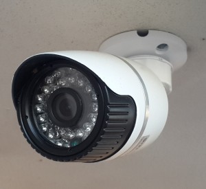
IP cameras have become really cheap and easy to come by, giving us many options to integrate video into our home automation systems. The front door is a great place to install a camera!

ip

The Digital Lifestyle has a very good write up on how to install and configure an add-on to display the camera overlay (especially if you have more than one camera) directly in Kodi itself.

We can then use some Python code to trigger the add-on using Kodi’s API.

Prerequisites: In Kodi, make sure “Allow control of Kodi via HTTP” is set to ON in Settings -> Services -> Webserver.

I wrote a small XBMC / Kodi client to make it easier to make calls to the API. Here is the method for triggering an add-on:

    def execute_addon(self, addon_id):
        payload = self._get_payload("Addons.ExecuteAddon",
{'addonid': addon_id})
        self._do_post_request(payload)

And here is the code for instantiating the client and executing the add-on:


xbmc_client = xbmc.XbmcClient(host, port)
xbmc_client.execute_addon("script.frontdoorcam")

On line 1, we instantiate the XBMC client by specifying the host and port. The port is configured in Kodi’s Settings -> Services -> Webserver -> Port.

The only parameter we are passing to the execute_addon method is the ID of the add-on we wish to run. Set it to the add-on ID that you specified in the addon.xml file.

That’s it. Next, we’ll look at how to build a text to speech server using Tornado.

The Raspberry Pi Powered Speaking Doorbell – Part 1: The Input Circuit

<< Previous post – The Raspberry Pi Powered Speaking Doorbell – Video

The first step of building the Raspberry Pi-powered speaking doorbell is building a simple input circuit. The purpose of the input circuit is to protect the Pi from damage by electrically isolating the doorbell and its power supply from the Raspberry Pi itself.

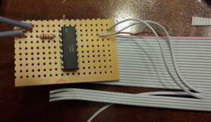
The circuit design and a full description of how it works can be found here. The power supply I used is rated at 12V, but the LTV-847 optocoupler used in the design copes just fine with an input voltage of 12V. It is a 4 channel optocoupler, so you can read 4 different inputs using the same optocoupler. I like using veroboard / stripboard for my circuits because the soldered connections are a bit more robust than a breadboard setup.

Input Circuit

Input Circuit – Top view

On the left are the 2 single-core cables that are connected to my doorbell and its 12V power supply. The + (anode) of the 12V power supply is wired to my doorbell button which in turn is connected to the input circuit (top left cable). The bottom-left cable on the input circuit is then connected to the – (cathode) of the power supply.

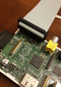
On the right-hand side, you’ll notice a ribbon cable. I have a model B Raspberry Pi, which has a 26 pin P1 header. I bought a 26pin IDC crimp connector and some ribbon cable, which fits perfectly on the P1 header.

IDC

The red cable indicates Pin 1 on the Raspberry Pi, so in the input circuit picture, the top right cable is connected to the 22nd cable of the ribbon cable (which corresponds to pin 22 on the Raspberry Pi) and the bottom-right cable is connected to the 20th cable (pin 20 on the Pi).

GPIOs

(Diagram from eLinux.org)

As you can see from the pin mapping diagram, pin 22 is GPIO 25 and pin 20 is Ground.

Input Circuit - Bottom view

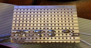
Input Circuit – Bottom view

You’ll notice on the bottom view of the input circuit that the tracks on the stripboard is scratched off between the input and output sides of the optocoupler. It is a good idea to test with a multimeter to make sure there is no continuity when measuring on either side of the “break” in the track to be sure that the connection is properly broken.

If you are like me and your soldering skills are not great, I would recommend testing the circuit before connecting it to your Pi. Get a friend to press your doorbell button while you measure continuity on the output side of the optocoupler – when the doorbell is pressed, the output side should be closed. When it is not pressed, it should be open.

I also like to test to make sure there is no continuity between consecutive tracks on the stripboard to make sure I didn’t accidentally solder a connection between tracks.

In the next post – how to display the camera overlay in Kodi.